Sunday, 20 July 2014

Simplest form of PRIVATE--VLAN


    Private-Vlans :-


 Private-vlan is an important security related concept.


Private-vlan --
|
|
|---Primary Vlan - There will be one primary for every secondary vlan. All secondary                                                       vlan  can communicate  with the primary vlan.
|
|---Secondary Vlan - Every Secondary vlan will communicate with only primary vlan.                                                    No two secondary vlan will communicate with each other.                                   


                                   Types of secondary vlans 
                                                  |
                                                  |
                                             /        \
                                         /               \
              Community Vlan               Isolated Vlan
All pc's with in community vlan      All pc's with in isolated vlan 
will communicate each other.             will not communicate with each other    


Private Vlan's Configuration with every command explanation :-


# Vtp mode transparent ( Private-vlan will work only in this mode of vtp )

# vlan 10
# private-vlan community  à making vlan 10 as community vlan
# exit


# vlan 20
# private-vlan isolated à making vlan 20 as isolated vlan
# exit

# vlan 100
# private-vlan primary à making vlan 100 as primary
# private-vlan association 10,20 à associating 10,20 ( secondary vlan           
# exit                                                                                to primary )

# int range f 0/1 -2
# switchport mode private-vlan host à making the port access mode
# sw private-vlan host-association 100 10 à putting the port into specific vlan , first the primary and                                                                                   then the secondary vlan
#exit 

# int range f 0/3-4
# switchport mode private-vlan host
# sw private-vlan host-association 100 20
# exit

# int f 0/5 à interface where router/ server is connected
# switchport mode private-vlan promiscuous à making port as trunk
# switchport private-vlan mapping  100 10,20 à which vlan’s to be allowed from promiscuous port ,                                                                                 ( first primary then secondary )
# exit


To verify

#show vlan private-vlan

Primary Secondary Type              Ports
-------      --------        ---------           -----------------------------------------
100        10                community    fa 0/5, fa0/1, fa 0/2       
100        20                isolate            fa0/5, fa0/3, fa 0/4


Tuesday, 8 July 2014

FTP and DNS


   What are the modes of FTP? 

A)  File Transfer Protocol, we use ftp in the process of transferring file from one device to the other.

On any system we can simply install FTP server software and it starts working like a FTP server. In terms of networking we use it for downloading or uploading the ios images from the routers mostly ( Not a very prominent use of ftp ).  Very effective between the transfer of files between the Server and Client. 

   There are two types of FTP.

Passive FTP: - In passive mode, the client establishes both channels (Data and control). In that case, the server tells the client which port should be used for the data channel.


Active FTP: - In active mode, the client establishes the control channel but the server establishes the data channel.


   What are the ports of DNS?


  Domain Name Server.

  DNS server is normally user to convert the IP-ADDRESS into NAME, and vice versa. 
 
    DNS use Port TCP & UDP 53.

  UDP/53 is used when a host or a router wants to resolve a domain name to an IP address (or vice versa).

  TCP/53 is used between two DNS servers when they want to sync or share their databases. Or If the size of the response message is more than 512 bytes, a TCP connection is used.

An example of DNS Lookups


Sunday, 6 July 2014

IP - SEC

IP- Sec is the most used tunnel in creating the VPn site-to-site tunnel.


IKE - ( Internet Key Exchange Protocol )
  
Internet key Exchange 

  • It automates the negotiations process of the S.A.
  • Dead Peer Detection : Hello Timer 10 Sec.
In Which two major protocols are involved - 1) Isakmp 2) DH - Group

ISAKMP -  ( Internet Security Association and Key Management Protocol )

  • This protocol is used for the exchange of the POLICY and Transform Set's, S.A related to the IpSec tunnel formation.
DH-GROUP - ( Deffie Hellman Algorithum )

Used for the Exchange of the PASSWORD'S between two devices to establish  a  shared secret  over an unsecured communication like isakmp for IPSEC.

DH consists of the following options:
  • D-H Group 1 — 768-bit DH Group.
  • D-H Group 2 — 1024-bit DH Group. This group provides more security than group 1, but requires more processing time.
  • D-H Group 5 — 1536-bit DH Group. This group provides more security than group 2, but requires more processing time.


Hashing -

A process of date integrity with out the process of encryption. It makes sure that the date is not tampered till it is delivered to the destination by generating and verifying the HMAC values.


Which supports two types of protocols : MD5 and SHA.


Encryption -

A process of converting simple clear text into ----> cypher text ( which is not understandable by humans )

Used for the protection of the data.

Algorithms used are DES, 3DES, AES

Des -


3DES-


AES - 


ESP -  ( Encapsulation Security Payload )

Esp supports Encryption, Hashing, Authentication, Encapsulation and Optional Anti replay


AH - ( Authentication Header )

Ah supports Hashing, Authentication, Encapsulation and Optional Anti replay.

The only difference between ESP and AH is encryption process.


Two basic modes 1) Tunnel Mode 2) Transport Mode

Tunnel mode is used between TWO sites , where the encapsulation will take place ( adding a new header )

Transport mode is used with in the site, where there is no encapsulation.


Thursday, 5 June 2014

Monitoring Your Network 


TCPView Tool
  1. Download the Tcpview Software, from the following link
      http://filehippo.com/search?q=Tcpview+Software
  2. TCPView is a Windows program that will show you detailed listings of all TCP and UDP endpoints on your system, including the local and remote addresses and state of TCP connections.
  3. TCPView also reports the name of the process that owns the endpoint. TCPView provides a more informative and conveniently presented subset of the Netstat program that includes with Windows.

    [Image: bb897437.tcpview(en-us,MSDN.10).jpg]
  4. The TCPView download includes Tcpvcon, a command-line version with the same functionality.
Tcpvcon Utility command
  1. Tcpvcon usage is similar to that of the built-in Windows netstat utility:
Code:
tcpvcon [-a] [-c] [-n] [process name or PID] -a    Show all endpoints (default is to show established TCP connections).
-c    Print output as CSV.
-n    Don't resolve addresses..
we can use the commands in simple command prompt of windows
Netstat Utility in Windows
  1. To display both the Ethernet statistics and the statistics for all protocols, type the following command:
    Code:
    netstat -e -s
  2. To display the statistics for only the TCP and UDP protocols, type the following command:
    Code:
    netstat -s -p tcp udp
  3. To display active TCP connections and the process IDs every 5 seconds, type the following command:
    Code:
    nbtstat -o 5
  4. To display active TCP connections and the process IDs using numerical form, type the following command:
    Code:
    nbtstat -n -o
  5. Store results of Any scan in text file:
    Code:
    netstat /a /n /o >c:\netstat.txt
Resolve common Netstat Utility Errors in Windows
  • If you just Goto Run > cmd > and type netstat it will show following Error:
    ‘netstat’ is not recognized as an internal or external command
  • Netstat Utility Runs with following directory:
    C:\WINDOWS\system32
  • Goto above directory & Type netstat commands then it will not show Errors.
  • Other way To Run this utility Which is: Directly press ctrl+r and Run netstat commands.
  • For More Help on Netstat utility type following command in ‘cmd’
    Code:
    netstat ?

Cisco IOS SPAN and RSPAN


Cisco Catalyst Switches have a feature called SPAN (Switch Port Analyzer) that lets you copy all traffic from a source port or source VLAN to a destination interface. This is very useful for a number of reasons:
  • If you want to use wireshark to capture traffic from an interface that is connected to a workstation, server, phone or anything else you want to sniff.
  • Redirect all VoIP calls from a VLAN so you can record the calls.
The source can be an interface or a VLAN, the destination is an interface. You can choose if you want to forward transmitted, received or both directions to the destination interface.
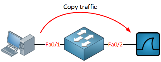
Cisco SPAN Example
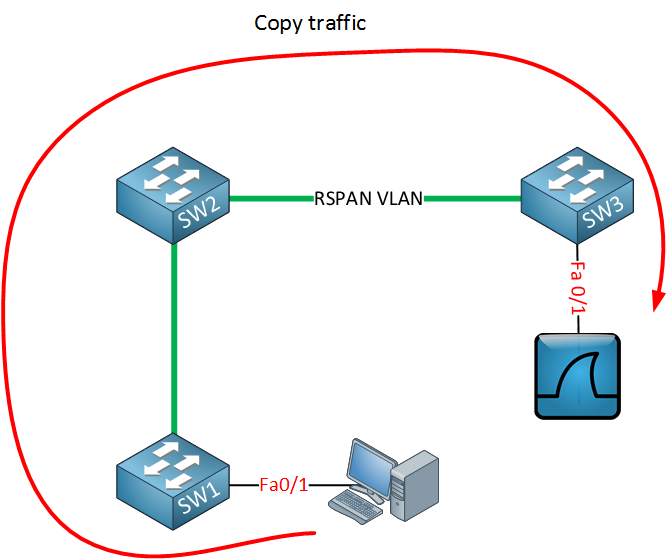
When you use a destination interface on the same switch as your switch we call it SPAN, when the destination is a remote interface on another switch we call it RSPAN (Remote SPAN).  When using RSPAN you need to use a VLAN for your RSPAN traffic so that traffic can travel from the source switch to the destination switch.
Cisco Switch RSPAN Example
When you use RSPAN you need to use a VLAN that carries the traffic that you are copying. In the picture above you see SW1 which will copy the traffic from the computer onto a “RSPAN VLAN”. SW2 doesn’t do anything with it while SW3 receives the traffic and forwards it to a computer that has wireshark running. Make sure the trunks between the switches allow the RSPAN VLAN.
SPAN and RSPAN are great but there are a couple of things you need to keep in mind…

Restrictions

Both SPAN and RSPAN have some restrictions, I’ll give you an overview of the most important ones:
  • The source interface can be anything…switchport, routed port, access port, trunk port, etherchannel, etc.
  • When you configure a trunk as the source interface it will copy traffic from all VLANs, however there is an option to filter this.
  • You can use multiple source interfaces or a single VLAN, but you can’t mix interfaces and VLANs.
  • It’s very simple to overload an interface. When you select an entire VLAN as the source and use a 100Mbit destination interface…it might be too much.
  • When you configure a destination port you will lose its configuration. When you remove SPAN, the configuration is restored. In short…you can’t use the destination interface for anything else besides receiving traffic.
  • Layer 2 frames like CDP, VTP, DTP and spanning-tree BPDUs are not copied by default but you can tell SPAN/RSPAN to copy them anyway.
This should give you an idea of what SPAN / RSPAN are capable of. The configuration is pretty straight-forward so let me give you some examples…

SPAN Configuration

Let’s start with a simple configuration. I will use the example I showed you earlier:
Cisco SPAN Example
123
Switch(config)#monitor session 1 source interface fa0/1
Switch(config)#monitor session 1 destination interface fa0/2
You can verify the configuration like this:
Switch#show monitor session 1
Session 1
---------
Type                   : Local Session
Source Ports           :
    Both               : Fa0/1
Destination Ports      : Fa0/2
    Encapsulation      : Native
          Ingress      : Disabled
As you can see, by default it will copy traffic that is transmitted and received (both) to the destination port. If you only want the capture the traffic going in one direction you have to specify it like this:
Switch(config)#monitor session 1 source interface fa0/1 ?
  ,     Specify another range of interfaces
  -     Specify a range of interfaces
  both  Monitor received and transmitted traffic
  rx    Monitor received traffic only
  tx    Monitor transmitted traffic only
Just add rx or tx and you are ready to go. If interface FastEthernet 0/1 were a trunk you could add a filter to select the VLANs you want to forward:
Switch(config)#monitor session 1 filter vlan 1 - 100
This will filter VLAN 1 – 100 from being forwarded. If you don’t want to use an interface as the source but a VLAN, you can do it like this:
Switch(config)#monitor session 2 source vlan 1
Switch(config)#monitor session 2 destination interface fa0/3
I am unable to use session 1 for this because I am already using source interfaces for that session. It’s also impossible to use the same destination interface for another session. This is why I created another session number and picked FastEthernet 0/3 as a destination. So far so good? Let’s look at RSPAN!

RSPAN Configuration

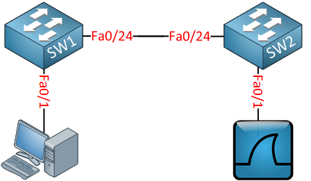
To demonstrate RSPAN I will use a topology with two switches:
Cisco RSPAN SW1 SW2
The idea is to forward traffic from FastEthernet 0/1 on SW1 to FastEthernet 0/1 on SW2. There are a couple of things we have to configure here:
SW1(config)#vlan 100
SW1(config-vlan)#remote-span
SW2(config)#vlan 100
SW2(config-vlan)#remote-span
First we need to create the VLAN and tell the switches that it’s a RSPAN vlan. This is something that is easily forgotten. Secondly we will configure the link between the two switches as a trunk:
SW1(config)#interface fastEthernet 0/24
SW1(config-if)#switchport trunk encapsulation dot1q
SW1(config-if)#switchport mode trunk
SW2(config)#interface fastEthernet 0/24
SW2(config-if)#switchport trunk encapsulation dot1q
SW2(config-if)#switchport mode trunk
Now we can configure RSPAN:
SW1(config)#monitor session 1 source interface fastEthernet 0/1
SW1(config)#monitor session 1 destination remote vlan 100
This selects FastEthernet 0/1 as the source and VLAN 100 as the destination…
SW2(config)#monitor session 1 source remote vlan 100
SW2(config)#monitor session 1 destination interface fastEthernet 0/1
And on SW2 we select VLAN 100 as the source and FastEthernet 0/1 as its destination. Here’s the output of the show monitor session command:
SW1#show monitor session 1
Session 1
---------
Type                   : Remote Source Session
Source Ports           :
    Both               : Fa0/1
Dest RSPAN VLAN        : 100
SW2#show monitor session 1
Session 1
---------
Type                   : Remote Destination Session
Source RSPAN VLAN      : 100
Destination Ports      : Fa0/1
    Encapsulation      : Native
          Ingress      : Disabled
T0 all so ever it may concern  to . I hope this example is been helpful to you! If you enjoyed this article and are studying for CCNP SWITCH, you might enjoy reading the article.  Feel free to leave a comment if you have any questions.

Friday, 9 May 2014

ATM NETWORK TECHNOLOGY

ATM (Asynchronous Transfer Mode) is a high speed network technology that has become the standardized solution for the telecommunication industry, teleconferencing, videoconferencing, telemedicine, HDTV, distance learning and where high speed data transfer is required.   ATM technology integrates voice, data and video at the same time. ATM uses fixed size packets called cells of 55 bytes in length. ATM network is a high speed circuit switched network that is capable of transferring one million signals using ATM protocol. ATM is a connection oriented technology in which logical connections are established for the data communication. ATM is implemented in the WAN and telecommunication sectors. Small data cells are used for communication and ATM is designed for high speed and high traffic networks. ATM cells allow voice, data and video transfer at the same time. ATM operates on the data link layer of the OSI model and it uses UTP/STP, fiber optic or air as a communication medium.

ATM CELL BASE
It is a small unit of 55 bytes fixed length and it contains the users and signaling information in it. It has a header with very limited functionality to reduce the internal buffer and to provide the high speed transfer. ATM cell identify the cells that belongs to the same virtual channels and perform easy routing.
  
ATM SWITCHING
Various switching technologies have been developed in the past to provide the high speed data transfer and secure communication. ATM switching technology provides high speed data transfer due to the connection oriented technology. ATM switching technology uses the predefined routing table so guarantees the fast data communication.
ATM DEVICES
ATM basically uses two types of devices such as ATM switch and end systems. The function of the switch is to handle the transmission of the cells throughout the network. Switches accept the incoming cells from the ATM end station or another ATM switch. On the other hand, ATM end systems contain the ATM adaptors.
ATM CONNECTIONS
ATM supports two types of connections point to point and point to multi point connections. In the point to point connections, two end systems are connected bi directionally or uni directionally. The point to multi point system connects one source to the number of destinations in uni directional. The source sends the information and switch replicates it to the destinations. Unidirectional network connects two switches. A typical ATM network consists of a set of the switches interconnected by point to point links. Switch support two types of interfaces user network and network node interface. Asynchronous transfer mode technology is designed for the reliability, performance, utilization and QOS and it creates fixed channels and routes when data travels between two points. There are four types of the choice when purchasing a connection.
Constant Bit Rate: It specifies fixed size rate and data is transferred in a steady form. Variable bit rate.
Variable Bit Rate: It provides specified throughput and it is best for videoconferencing.
Available bit rate. It provides guaranteed minimum capacity but high rate is also possible when the network is free.
Unspecified bit rate. It does not provide any fixed throughput level and it is best for the file transfer where delay can occurred.
ATM ADVANTAGES
It provides fixed bandwidth and simple routing is possible due to the connection oriented technology. High bandwidth utilization can be possible so it is the best solution for the telecommunication sector, videoconferencing and QOS. There are some of the disadvantages of this technology such as high cost, cell loss due to the high congestion in the network.

What is WAN Optimization ??

How to Optimize WAN
Networks play an important role in the businesses and if the network is slow so is the business. For improving the performance there are different techniques and products are on the rise such as route control products, content delivery networks, load balancing technology, multicasting and caching.
The other techniques and methods that are involved in improving the performance of the wide area network are CIFS proxy, HTTPS proxy, media multicasting, bandwidth management, web casting and WAFS.  Deployment of the wide area network optimization appliances at the data center and the branch sites boosts the network and distributed application performance with the minimum efforts.
Improving applications performance over the networks has become the ultimate goal of the organizations.  Varying network types and applications require different solutions.  WAN accelerators and WAFS optimize the data that travel over the longer distance.  Traffic over the wire is optimized through streaming, compression, prioritization, local and centralized caching and other methods.

Optimization Techniques
The optimization software and hardware use the following techniques to boost the performance of a network.
  • Staging data on the local cache
  • Compressing and prioritizing data
  • Streamlining chatting protocols.
Vendors
The following vendors provide the WAN optimization products and appliances.
  • Cisco
  • Juniper
  • Blue Coat
  • F5 Networks
  • Silver Peak
  • River Bed
  • InMage
  • Peribit
Most of the products provided by these vendors are the hardware based and some are the combination of hardware and software.
Juniper offers the following Networks Application Acceleration Platforms.
  • WX Platforms
This platform is used to increase the application performance, application and data prioritization, WAN capacity and this platform delivers compressed output that travels at the speed 64 Kbps to 155 Mbps.
  • WXC Platforms
WXC Platforms holds the on-board hard drives that are used to store the repeated data and that ultimately increase the WAN capacity by 100 folds.  WXC Platforms support the disk capacity from 40 GB to 3 TB and WAN links from 128 Kbps to 155 Mbps.
  • WX CMS
WX CMS platform is used to manage multiple WX platforms and WXC platforms from one central location.  There are easy monitoring and configuration tools in this platform.  The main feature of the WX CMS is the application performance, WAN utilization, bandwidth allocation and QOS.